Note
This technote is not yet published.
Fibers deployed at the Summit
1 Introduction
The purpose of this document is to provide information related to the installation, materials used, network point areas, and the number of fiber filaments used per floor. This documentation also reflects how the physical network of the calibration hill, main generator room and Villa Pachon is built by putting an emphasis on the fact that the project is still undergoing construction and will undergo continuous changes in the near future. These changes include additional network points or removing those that are already in place. The materials used for this project were all selected based on their quality and technical properties so that the project can operate at maximum performance in the operations phase.
2 Current Deployment
2.1 Materials Used
2.1.1 Fiber:
Single-mode fiber was selected and installed due to its technical properties hence it provides an unlimited transmission limit. This fiber will only be used for the equipment that functions as a transmitter (TX) and receiver (RX).
In some occasions, multi-mode fiber cable connections will be set up and installed for any technical equipment that requires it.
2.1.2 Copper:
It is also noted that UTP S/FTP cables were also selected due to the cable properties and ability to work at 10GBASE-T speeds. All network points were installed with this type of cable, both the access points and telephony connection systems. In regard to end-user devices, UTP CAT6 was setup.
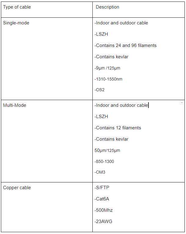
2.1.3 Component Features
3 Areas of interest
- Calibration Hill
- Main Generator room
- Villa Pachon
This document explains briefly the various connections used, both copper and fiber for the areas located in Cerro Pachon.
As a reminder, all fiber optic connections are born inside the second floor of the computer room in rack A7. In this rack, all-optical headers are concentrated and connect to different areas of the calibration hill and villa pachon.
4 Calibration Hill
The calibration hill is composed of the following areas:
- Auxtel
- Weather Tower
- DIMM
- All Sky Camera
4.1 Exterior Calibracion Hill
The areas listed above are all connected with a 24 Fiber optic filament cable that comes from the computer room located in the main building.
A Fiber optic splice enclosure (MUFA) was used on the calibration hill, the fiber optic filaments inside the MUFA were separated into 4 separate fiber optic cables. Each one of these cables was routed towards each location as shown in the image below.
4.1.1 Calibration Hill image
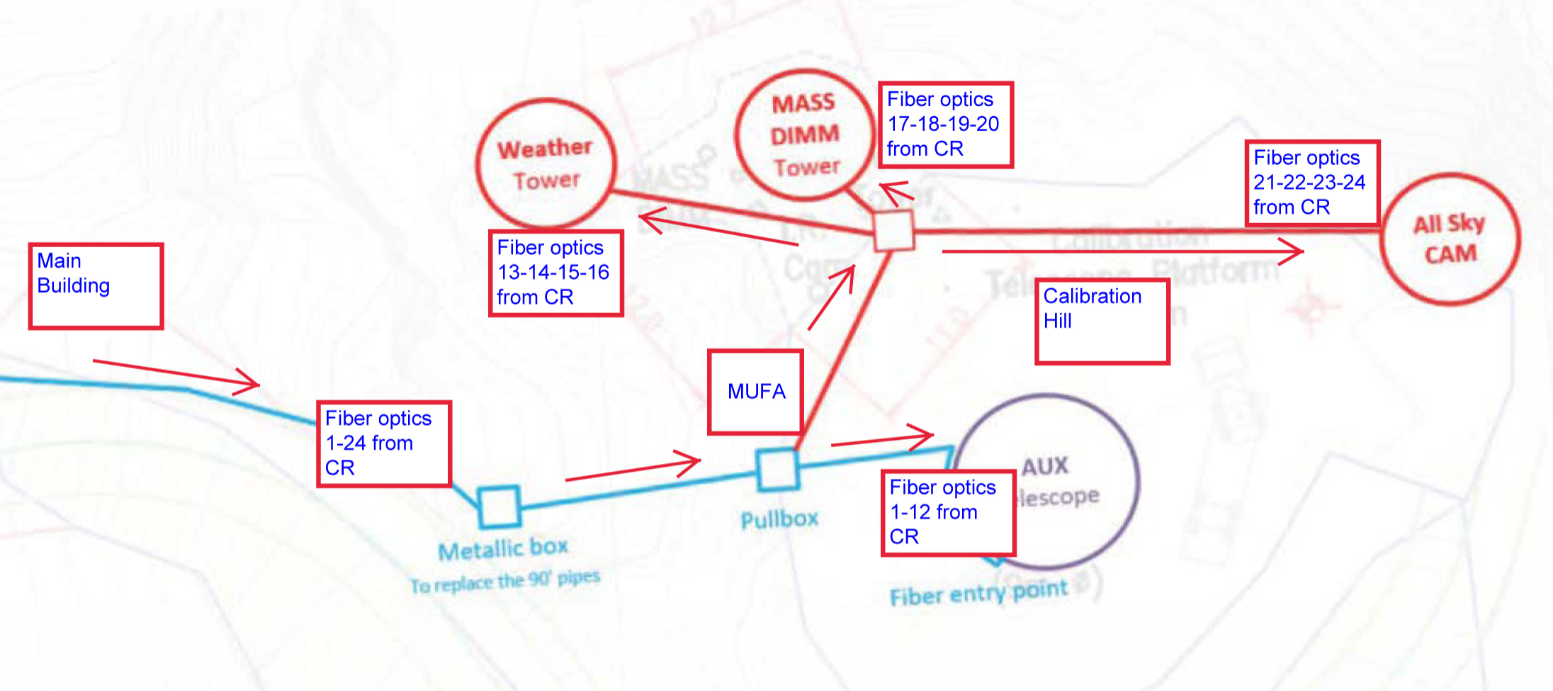
The fiber optic filaments were numbered and broken down the following way:
- (1 - 12) Fiber optics for AuxTel
- (13-14-15-16) Fiber optics for Weather Tower
- (17-18-19-20) Fiber optics for DIMM
- (21-22-23-24) Fiber optics for All Sky Camera
4.2 Calibration Telescope
The calibration telescope building consists of two floors, in this area there are 12 single-mode fiber-optic connections that exit the optical splice enclosure (MUFA) located at the calibration hill, these fiber optic connections make their way towards the optical terminal located in the calibration telescope. These fiber-optic connections have an optical header that’s located inside the Auxtel rack and utilize LC/UPC full-duplex connectors.
In the Auxtel building, the floors have the following characteristics in terms of the materials used and the numbering of the various network points.
Auxtel
- 35 Network points in total
- 2 Access points
- 1 Boxed VoIP
- 2 24-port patch panel with modular jack, category 6A
- 1 Optical header with 12 SM OS2 optical fibers and LC Full-Duplex UPC connectors
- 2 24-port switch
- 1 42U rack
- 2 PDUs
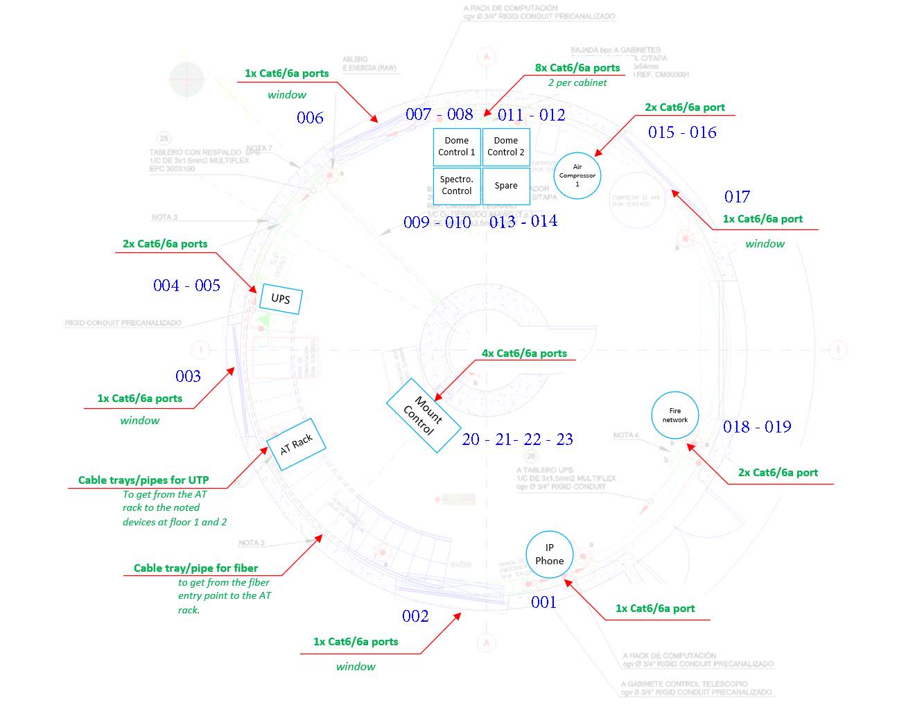
The following network diagram illustrates the connections and components used for both the first and second floor of the Auxtel building utilizing the same rack.
4.2.1 First Floor Image:
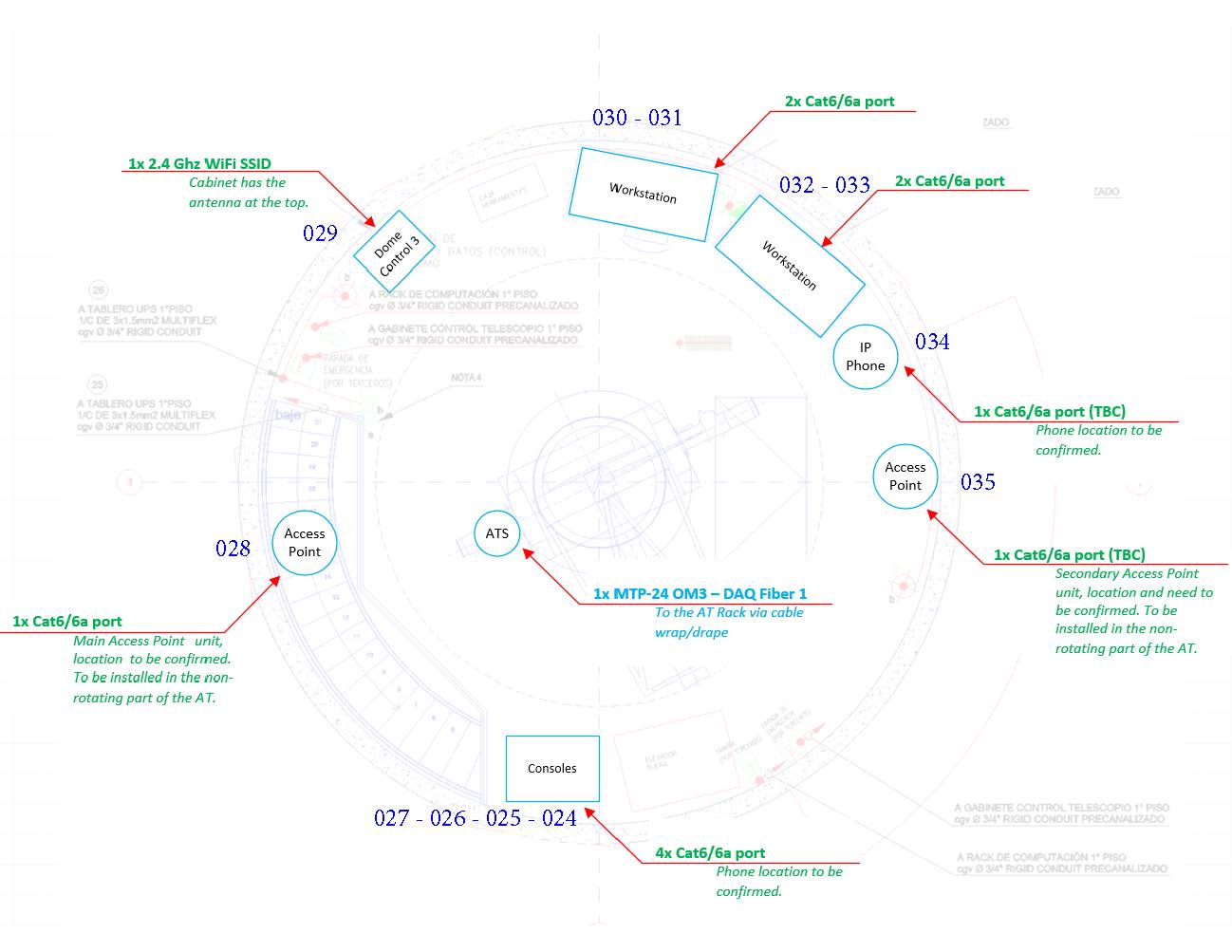
4.2.2 Second Floor Image:
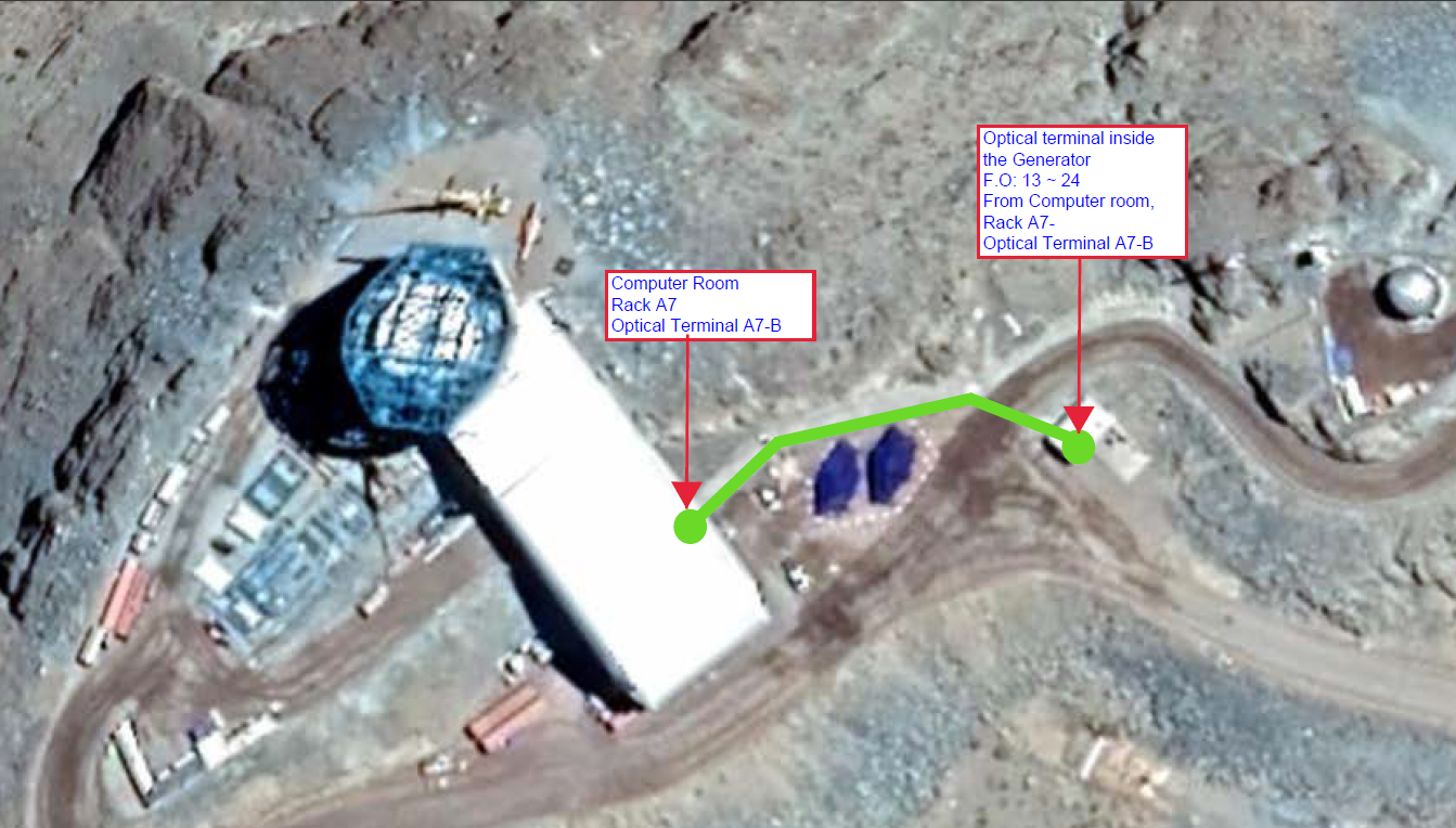
5 Main Generator Room
The idea to connect the main generator room was born from the necessity of monitoring the generator during use.
IT installed 24 single-mode fiber optic filaments where 12 of them are connected to the optical terminal located inside the main generator room. As for the other 12 filaments were left available for use in case any other future requirements are born.
It is also important to mention that an industrial 8 port switch was also installed in the main generator room inside a protective box. The purpose of this switch was to set up a phone in case of any emergencies or activities that require its use. Additionally an access point and a camera were set up for surveillance and wifi connectivity all inside the main generator area.
The backbone of this connection comes from the second floor, passes through the optical terminal located on the first floor of the main building, and continues its way towards an optical terminal located inside the main generator room where the box with the switch is located.
Generator room network components:
- 1 Camera Connection
- 1 Access point Connection
- 1 VoIP Connection
- 1 Monitoring connection to the Generator
Note: All of these connections were made with CAT6 and CAT6A cables and come directly from the industrial switch located inside the main generator room.
5.1 Main Generator Image
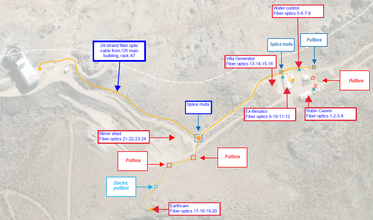
6 Villa Pachon
The need to connect Villa Pachon to the computer room located inside the main building arose from the fact that the current connection was not reliable enough in this sector. Additionally, other areas inside the Villa which did not have connectivity were also incorporated into this connection to the computer room.
To carry out this task, IT installed 24 Fiber Optic filaments backbone cable from the computer room in rack A7 towards the sector known as Villa Pachon in which its divided in to the following areas:
- Rubin Casino F.O 1-2-3-4
- Water Control F.O 5-6-7-8
- Ex-Besalco F.O 9-10-11-12
- Villa Generator F.O 13-14-15-16
- Earthcam F.O 17-18-19-20
- Mirror Shed F.O 21-22-23-24
As to this year 2020 the following areas are connected and operational.
- Ex-Besalco (Completed)
- Villa Generator (Completed)
7 Activities planned for FY21/22
7.1 Villa Pachon
For FY21/22 we expect to connect the remaining areas to the 24 Fiber Optic backbone cable.
- Rubin Casino F.O 1-2-3-4 (Pending)
- Water Control F.O 5-6-7-8 (Pending)
- Earthcam F.O 17-18-19-20 (Pending)
- Mirror Shed F.O 21-22-23-24 (Pending)
The image below illustrates the sector considered as the “Villa Pachon project”, it also shows how the project will look like in the future once its finished and all fiber optic connections are setup and installed.
7.2 Villa Pachon Image for FY21/22
8 Acronyms
| Term | Meaning |
|---|---|
| 10G | 10 Gigabits |
| AP | Access Point |
| Auxtel | Auxiliary Telescope |
| AWG | American Wire Gauge |
| AURA | Associated Universities for Research in Astronomy |
| BDC | Base Data Center |
| CAT | Category |
| DWDM | Dense Wavelength Division Multiplexing |
| FY | Fiscal year |
| IEEE | Institute of Electrical and Electronics Engineers |
| IT | Information Technology |
| LAB | Laboratory |
| LC | Little Connector or Lucent Connector |
| LSZH | Low smoke zero halogen |
| MM | Multi-mode |
| MHZ | Megahertz |
| OM1 | Optical Multi-mode the number is the CAT of the cable |
| OM3 | Optical Multi-mode the number is the CAT of the cable |
| OS2 | Optical Single-mode the number is the CAT of the cable |
| S/FTP | Shielded/Foiled Twisted Pair |
| SM | Single-mode |
| TX | Transmission |
| UTP | Unshielded Twisted Pair |
| UPC | Ultra Physical Contact |
| UPS | Uninterruptible Power Supply |
| VoIP | Voice Over Internet Protocol |
| µm | Microns |
| nm | Nanometer |